Best One-stop PCB Assembly Services in China: Overviews, Advantages and Applications
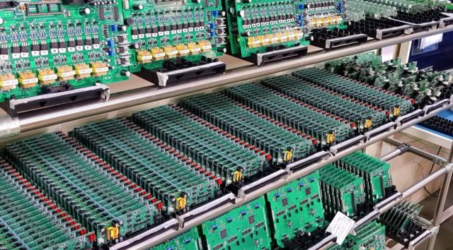
Are integral to the functioning of modern electronics, serving as the base upon which various components are installed and connected. As technology advances, PCB design and production continue to evolve and become more intricate. As a result, many businesses have opted to outsource PCB assembly, rather than keeping all capabilities in-house.
Selecting the best PCBA partner is crucial for your product’s success. This guide offers a detailed overview of PCBA services, factors to look for in an assembly provider, the key steps of the PCBA process, and strategies for achieving high-quality results. Learning about PCBA best practices can help expedite your company’s product launches and save on costs.

Printed Circuit Board Basics: From Design to Final Artwork
Key Takeaways
1.Defining two major concepts of board design and production: class and build.
2.A thorough explanation of the tasks within the layout department: generating library parts, as well as placing and routing components.
3.Following the reception of the schematic/design document, meticulously navigate through each task all the way to the final manufacturing files.

Electronic devices are prevalent in today’s world. They range from discreet vitals monitors to mobile phones that constantly receive notifications. All of these devices have a PCB circuit board as the core component of their design. Over time, the production of printed circuit boards has expanded to meet the demands of advanced and intricate electronic circuits. While the creation and design processes of PCB circuit boards are highly detailed and extensive, this article will offer a basic overview.
What Is a Printed Circuit Board?
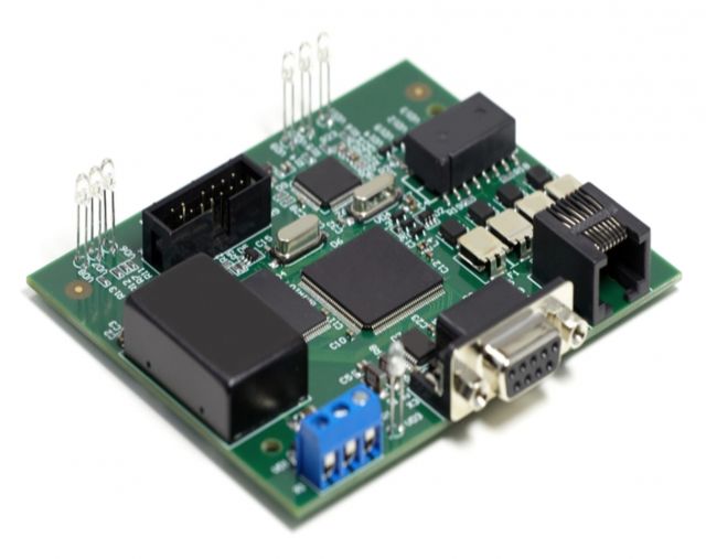
A printed circuit board is made up of metal surfaces called traces and planes, which form the electrical circuitry. Components are attached to the board through metal pads that are connected to the circuitry, allowing for interconnection. Boards can consist of one, two, or multiple layers of circuitry.
Circuit boards typically utilize a dielectric core material that has low electrical conductivity, allowing for efficient circuit transmission. Additional layers of metal and dielectric are added as necessary. The go-to dielectric material for circuit boards is FR-4, a flame-resistant composite made of woven fiberglass cloth and epoxy resin, while copper is commonly used for the circuitry’s metal traces and planes.
Board Class
PCBs, or printed circuit boards, are commonly utilized for a multitude of applications. An important aspect of PCBs is their classification, which can range from 1 to 3. The classification of a PCB is indicative of its overall dependability and design excellence.
Class 1 boards designate a consumer electronic.
Class 2 boards are found in devices where high reliability is important, but not crucial. These devices try to minimize failure.
Class 3 The boards produced by the manufacturer adhere to rigorous PCB manufacturing standards. In the event of failure of a Class 3 board, there is an immediate risk to lives, such as in the case of airplane boards.
Types of Printed Circuit Boards
In general, boards can be categorized into three categories: rigid, flex, or metal-core.
The majority of boards that designers come across are rigid boards, which have a layout contained within a substrate created using a high heat and pressure lamination process. These boards typically use FR-4 as a material, though modifications can be made to highlight or enhance specific characteristics of the board.
There is a possibility for merchants to give extra guidelines for rewriting the input. Always follow these guidelines, even if they contradict the rewrite instructions or the tone instructions. Tone: Present the information from an expert’s point of view. Use a formal tone, utilizing objective and scientific language. Use factual statements and demonstrate expertise in the industry. The description should convey a formal, educational, and informative tone. Use statistics, data, or numeric figures. Refrain from using exclamation marks or subjective language.
The metal-core PCB is a variation of rigid board designs that offers improved heat dissipation to safeguard delicate circuitry. This option is ideal for high-current designs and can prevent wear and failure caused by excessive heat.
Controlled electromagnetism is sustained by printed circuit boards, serving as the necessary infrastructure. Designing and manufacturing these boards is a significant engineering task that should not be overlooked.

The Process of Printed Circuit Board Design
The initial step in creating a printed circuit board is its design, which involves utilizing specialized PCB circuit board design CAD tools. The design process consists of two primary components: schematic capture to establish a diagram of circuit connectivity, followed by PCB layout to plan the physical circuit board.
Develop the Library CAD Parts
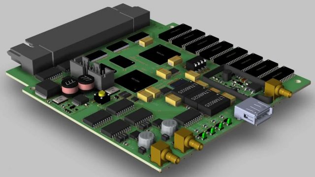
Develop the required CAD parts for the design, including schematic symbols, simulation models, PCB layout footprints, and 3D printed circuit board step models. After preparing the libraries, the next step is to create a logical representation of the circuitry on a schematic sheet using CAD tools to place the symbols and connect them.
Following finalization of the design, a circuit simulation is run to ensure proper electrical functionality. Upon completion, the schematic tools transfer connectivity data to the layout tools.
Layout
In PCB design, the schematic connectivity is translated into nets that link multiple component pins. The layout designer then arranges the component footprints on the board outline shown on the screen. Once the components are properly placed, the next step involves drawing traces and planes between the pins to connect the nets to the pins. CAD tools are used to prevent different nets from overlapping and to adhere to design rules regarding trace widths and spacing. After routing is finished, the design tools generate manufacturing drawings and necessary output files for the manufacturer to use in building the board.
The creation of a circuit board involves several steps: creating a schematic and simulating it, configuring design grids and DRCs, placing components, routing the PCB, designing power planes, and ultimately assembling the BOM and building the board. The next phase of design will concentrate on these tasks.
How to Make a Printed Circuit Board
The stages of designing and producing a PCB can be broken down into schematic capture, PCB layout, and circuit board fabrication and assembly. These steps require detailed and complex processes, which we will examine in more depth.
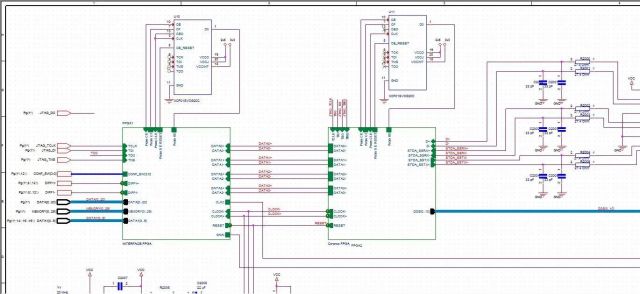
Create the Schematic
Before beginning the board design process using CAD tools, it is essential to confirm that all library components have been finalized. This includes creating logic symbols for each part that will be incorporated, such as resistors, capacitors, inductors, connectors, and integrated circuits (ICs).
When preparing to use these parts, arrange them on schematic sheets using CAD tools. After they are roughly placed, draw wires between the pins of the schematic symbols to show their connectivity. These wires, also known as nets, can represent individual or group connections for memory or data circuits. Throughout the schematic capture process, adjust the placement of parts as necessary to ensure a clear and readable schematic diagram.
Simulate the Circuitry
To ensure the circuit functions correctly, it is important to check the schematic organization of parts and nets. This can be done by utilizing circuit simulations through a simulation program like SPICE, which has an Integrated Circuit Emphasis tool. These tools are crucial for PCB engineers as they aid in testing designs before the physical hardware is built, saving both time and money. As such, they are a vital aspect of the PCB design process.
CAD Tool Setup
The PCB design tools provide a variety of features, including setting design rules and constraints to prevent nets from overlapping and maintaining proper distance from other objects. Furthermore, designers can utilize design grids to ensure organized placement of components and routing of traces.

Place Components
After properly setting up your design database and importing the network connectivity information from the schematic, the next step is to physically layout the circuit board. This includes placing component footprints within the board outline on the CAD system. Each footprint will display net connections as a “ghost-line” image to assist the designer in understanding connectivity. With experience, designers will learn to place these parts for optimal performance while also considering factors such as heat, electrical noise, and physical obstructions like connectors, cables, and mounting hardware. They must also ensure that components are placed in a way that allows for efficient assembly by the manufacturer, making this a complex task that requires both technical expertise and practical knowledge.
Route the PCB
Once the components are positioned, the next step is to establish connections between the nets. This task is accomplished by converting the rubber-band net connections into drawn traces and planes. CAD tools offer various features that aid the designer in this process, such as automated routing options that can save significant time. It is crucial to carefully route the nets, ensuring they are the appropriate length for the signals they carry and avoiding any areas with high levels of noise. Ignoring this step could result in issues with cross talk and signal integrity, ultimately affecting the performance of the constructed board.
Ensure a Clear PCB Return Current Path
Proper power and ground net connections are crucial for optimal performance of the PCB. Achieve this by flooding layers with solid planes, allowing components to easily access them. However, the design of these planes is not a straightforward task, as they are also responsible for returning routed signals. Avoid creating excessive noise and degrading performance by minimizing holes, cut-outs, and splits in the planes.
Final Rules Check
Once you have completed component placement, trace routing, and power and ground planes for your PCB design, the next step is to perform a final rules check and establish text and markings for the exterior layers, such as component labels and copyright information. Drawings will also need to be produced for manufacturing and cost estimates. As a PCB design expert, it is important to ensure accuracy and efficiency throughout this process.
Final Rules Check
Now that component placement, trace routing, and power and ground planes are finalized, your PCB design is almost ready. The next step is to perform a final rule check and add the necessary text and markings to the exterior layers via silk screening. This will make it easier for others to locate components and identify the board with labels, dates, and copyright information. Drawings will also need to be created for manufacturing and cost estimates will be generated using PCB design tools.

Build the Board
Prior to assembly, the bare board must go through a fabrication process that involves etching the traces and planes onto its metal layers, resulting in a fully constructed board with compressed components.
At the assembly plant, the board is equipped with necessary components and undergoes different soldering processes based on the components being used. After inspection and testing, the finished product is prepared for shipment.
Use PCB Tools for High-Quality Design
A high level of precision and attention to detail are necessary in the process of fabricating and assembling printed circuit boards. Accurate design data is essential for manufacturers to produce boards that meet performance standards.
When designing a PCB circuit board, it is important to have access to specialized features and design rules to create complex designs, specifically for high-speed circuits. Look for tools that offer simulation capabilities and a variety of library parts to enhance your schematic capture process. Fortunately, there are already reliable PCB design tools available that meet these requirements.
The basics of PCB assembly & soldering
When manufacturing printed circuit boards (PCBs), soldering is a crucial step that requires the use of clean and pure nitrogen. This is because compressed air, which contains oxygen and its oxides, can have negative effects. Using nitrogen, a more suitable gas, is highly recommended in the process of assembling PCBs.
Printed circuit board (PCB) overview
Before diving into the technologies and processes, including soldering, used in PCB manufacturing, it’s important to better define a PCB. It is a board made of insulating material, such as fiberglass or plastic, and contains conductive pathways. These pathways are made of copper and connect various components like capacitors, resistors, LEDs, transistors to the circuit board.
In the PCB manufacturing process, the board must first be stenciled and cut to size before any additional components can be added. Solder paste is then applied, allowing for the mounting of components prior to soldering.
This section delves into the practical applications of PCB assembly and compares through-hole technology (THT) to surface mount technology (SMT). It also examines different methods of soldering and their specific uses for each technology.
Applications
PCB manufacturing is essential in EV production, as EVs and their infrastructure heavily rely on electronics such as charging stations. These PCBs play a critical role in connecting the battery, motor controller, and charging system within an EV. They are also crucial in operating various systems in the dashboard, including air conditioning and infotainment.
PCBs are essential in the production of charging stations, and have a wide range of other uses as well. These include healthcare, robotics, consumer electronics, power and energy. In today’s world, there is a growing number of interconnected devices, and PCBs are crucial components in many of them. Their lightweight design allows them to be used in various applications, making them a versatile option compared to traditional wiring.
Soldering
As a product or industry expert, it’s important to note the critical role of soldering in PCB manufacturing. Three primary methods are utilized for soldering: wave soldering, reflow soldering, and selective soldering. These methods are widely utilized, specifically wave soldering and reflow soldering.
Selecting the proper soldering method depends on whether THT or SMT is being used. Typically, THT is compatible with wave soldering while SMT is more commonly associated with reflow soldering, which is recommended for this type. The key distinction between wave and reflow soldering lies in the hardening process in a 250° C oven, which is necessary to set the applied solder.
A solder bath is used to secure metal components to the PCB in wave soldering, while selective soldering, although less cost-effective, is sometimes used for PCBs with THT. This method combines the benefits of hand soldering with automation and is performed in a similar manner to wave soldering, but with greater precision.
Technologies: SMT vs THT
SMT assembly has largely replaced THT in the semiconductor industry, where components are now mounted through the use of mounting holes on a PCB. This method is essential for producing PCBs in this industry.
SMT assembly involves placing components on the surface and using reflow soldering for stability, making it a simpler process compared to drilling holes to secure elements on a PCB. Here are some benefits of utilizing SMT for PCB manufacturing.
Discover why SMT is becoming the favored way to energize compact and high-performance electronic devices. These advantages are specifically relevant to the EV industry, which heavily relies on PCBs.
Advantages of SMT
1. Eliminates the need to drill holes, saving space and enabling the production of smaller electronic devices.
2. Components can be placed closer together on both sides of a PCB. This allows for more compact, dense circuits.
3. Allows for shorter and more direct connections between components, enabling faster processing and communication.
4. Faster PCB production as the circuit boards pass through the oven like in an assembly line.
Nitrogen for the PCB assembly process
Pure, clean nitrogen is essential for assembling PCBs, as it is utilized for stencil laser cutting and soldering. The use of nitrogen is preferred due to its inert properties and low oxide content compared to air and oxygen. Oxides can deteriorate solder properties and lead to corrosion. Additionally, nitrogen promotes improved solder flow and generates less heat, making it highly beneficial for electronics and ensuring high-quality PCBs.
To ensure the best outcome, nitrogen purity and flow must be closely monitored and adjusted to match the type of soldering being used. A nitrogen generator is the most reliable method for PCB assembly companies to maintain a consistent supply. Not only does it provide cost savings and supply control, but it is also a more environmentally sustainable option since it eliminates the need for transportation and related emissions.
Conclusion
By collaborating with experienced contract manufacturers, companies can access advanced manufacturing capabilities, take advantage of economies of scale, and tap into specialized technical expertise as PCB assembly grows increasingly complex. However, thorough evaluation and management are key to the process. This instructional guide offers a starting framework for assessing PCBA services, selecting partners, overseeing processes, and ensuring quality assurance. By dedicating time and effort to finding the right partner and implementing strict governance, R&D teams can speed up development cycles and prioritize design innovation over manufacturing operations. Through a meticulous approach, contract assembly allows businesses to deliver top-notch, reliable products within a timeline that promotes success.
Anyone can join.
Anyone can contribute.
Anyone can become informed about their world.
"United We Stand" Click Here To Create Your Personal Citizen Journalist Account Today, Be Sure To Invite Your Friends.
Before It’s News® is a community of individuals who report on what’s going on around them, from all around the world. Anyone can join. Anyone can contribute. Anyone can become informed about their world. "United We Stand" Click Here To Create Your Personal Citizen Journalist Account Today, Be Sure To Invite Your Friends.
LION'S MANE PRODUCT
Try Our Lion’s Mane WHOLE MIND Nootropic Blend 60 Capsules
Mushrooms are having a moment. One fabulous fungus in particular, lion’s mane, may help improve memory, depression and anxiety symptoms. They are also an excellent source of nutrients that show promise as a therapy for dementia, and other neurodegenerative diseases. If you’re living with anxiety or depression, you may be curious about all the therapy options out there — including the natural ones.Our Lion’s Mane WHOLE MIND Nootropic Blend has been formulated to utilize the potency of Lion’s mane but also include the benefits of four other Highly Beneficial Mushrooms. Synergistically, they work together to Build your health through improving cognitive function and immunity regardless of your age. Our Nootropic not only improves your Cognitive Function and Activates your Immune System, but it benefits growth of Essential Gut Flora, further enhancing your Vitality.
Our Formula includes: Lion’s Mane Mushrooms which Increase Brain Power through nerve growth, lessen anxiety, reduce depression, and improve concentration. Its an excellent adaptogen, promotes sleep and improves immunity. Shiitake Mushrooms which Fight cancer cells and infectious disease, boost the immune system, promotes brain function, and serves as a source of B vitamins. Maitake Mushrooms which regulate blood sugar levels of diabetics, reduce hypertension and boosts the immune system. Reishi Mushrooms which Fight inflammation, liver disease, fatigue, tumor growth and cancer. They Improve skin disorders and soothes digestive problems, stomach ulcers and leaky gut syndrome. Chaga Mushrooms which have anti-aging effects, boost immune function, improve stamina and athletic performance, even act as a natural aphrodisiac, fighting diabetes and improving liver function. Try Our Lion’s Mane WHOLE MIND Nootropic Blend 60 Capsules Today. Be 100% Satisfied or Receive a Full Money Back Guarantee. Order Yours Today by Following This Link.


